

Gas Cherenkov Detector R&D
Design and Construction of a Prototype Cherenkov Detector
Based on the understanding (& simulation) of the SLD polarimeter Cherenkov detector, a new prototype detector was designed and constructed in 2008. The design of the prototype detector is based on the same set of requirements that also drives the design of the ILC polarimeter Cherenkov detectors:
- High and homogenous light yield
Cherenkov radiation is characterised by a 1/λ2 distribution, thus a high reflectivity is needed also for short wavelengths of λ ≈ 200-350 nm. This helps in obtaining a high light yield per Compton electron and keeping fluctuations small. All relevant detector surfaces should be as smooth and planar as possible to ensure a uniform light transmission and together with an adequate channel geometry help illuminating the photodetector homogeneously. - Gas- and light-tightness
In order to control the linearity to permille level accuracy and to achieve a stable response, it is indispensable for the entire detector system to be light- and gas-tight. The detector should be sufficiently tight to keep a stable pressure over several weeks without a permanent gas flow system. - Thin walls between channels
Electrons entering the channel walls are not only lost for Cherenkov detection, but might also initiate an electromagnetic shower and thus create background in the adjacent channels. Therefore the walls should be as thin as possible. - Robustness with respect to backgrounds
A gas with a Cherenkov threshold in the MeV-regime should be used to avoid the emission of Cherenkov light from low energetic electrons and muons, e.g. from the beam halo, from beam-gas interactions, or electrons pair-produced from synchrotron radiation. A layout allowing the photodetectors and electronics to be placed well outside the beam-plane is mandatory. - Calibration system
A dedicated calibration system is forseen to monitor the detector response, especially its linearity, in-situ. This could be realised by equipping the channels with light emitting diodes (LEDs) which should also be placed outside the beam-plane. Such a system could collect data during breaks in the accelerator operation, or even in-between two ILC bunch trains.
The last two requirements are satisfied by the channels’ U-shape. With increasing length of the U-base more
Cherekov light is produced, but on the other hand the alignment requirements become more stringent and additional
reflections will decrease the light yield. Simulations suggest that a length of 15 cm is a reasonable choice.
In contrast to the ILC-like design of 20 staggered channels
(see: Basics, Figure 3),
the prototype detector consists of only two parallel, non-staggered channels.
Apart from this difference, the smaller prototype detector allows to test all relevant aspects of the full detector.

Optical Simulation of the Prototype Detector
A detailed optical simulation based on GEANT4 accompanies the design and construction of the prototype detector.
It also serves to determine some of the key figures such as the photon yield per electron, the average number of
reflections and possible asymmetry effects due to the utilized materials or chosen geometry, especially the square
channel cross section.
Figure 1 shows an event display of the prototype simulation, more accurately: the internal channel structure with
a single electron (red) traversing the U-base of one detector channel from left to right. It emits Cherenkov light
(green), which is reflected upwards to a photodetector mounted on the hind U-leg.
Both channels are separated by a thin foil (light grey). Cherenkov light produced outside the channel structure
in the ambient gas of the surrounding box cannot reach the photodetectors.
The square channel cross section of 8.5x8.5 mm2 matches the anode layout of two multi-anode
photomultipliers (MAPMs) , such that one quadrant covers one detector channel. These MAPMs
were chosen based on earlier stand-alone studies of different photodetector types.
Construction of the Prototype Detector
The U-shaped channels are manufactured from diamond-milled aluminium with a 0.3 mm--thin separating wall of rolled aluminium. The basis of the channels is approximatly 15 cm in length. The produced Cherenkov light is reflected upward by 90 degrees at the end of the basis by a highly polished aluminium plate. The first leg of the channels holds an LED calibration system. Figure 2 shows the channel structure (left), which is placed inside a gas-filled aluminium box.

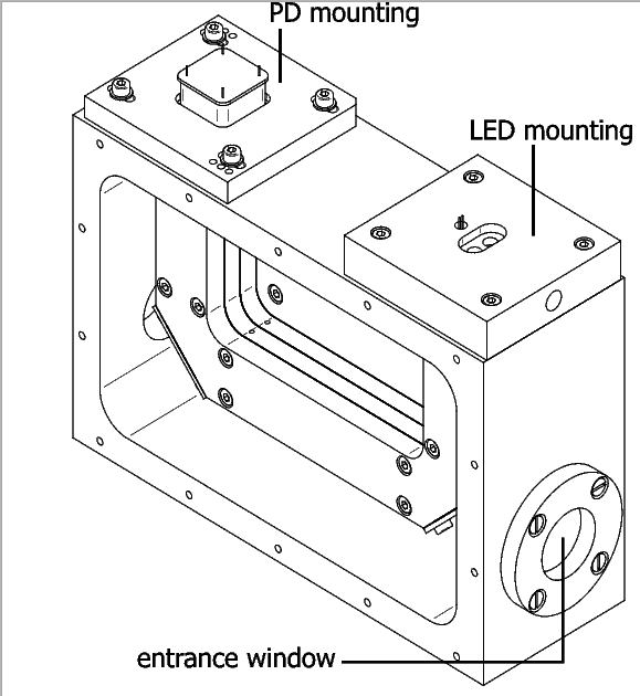
Placed inside the outer box
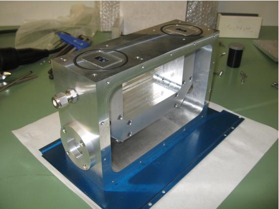
A photo of the open prototype box
Perfluorobutane (C4F10) was chosen as Cherenkov gas due to its high Cherenkov threshold of about 10 MeV for electrons. In addition it is neither flammable, nor explosive, contrary to propane or isobutane. The 10 mm--thick aluminium lid of the box holds an electronic pressure gauge suited for remote read-out. The entrance and exit windows for the electron beam consist of 0.5 mm--thin aluminium sheets of rolled quality.
Testbeam Measurements at ELSA in Bonn: 2009
The fully assembled protoype has been taken to the ELSA ring in Bonn in July of 2009 in order to make a series of first measurements. This testbeam period was intended to show the detector's capability for alignment from beam data, and to determine the detector response to varying extraction currents, with the ultimate goal to test the detector linearity.