

GEM
Gas Electron Multipliers (GEMs)

The GEM technology, which has been introduced by F. Sauli in 1996, is used in high energy and medical physics detectors to amplify an electron signal in a gaseous detector.
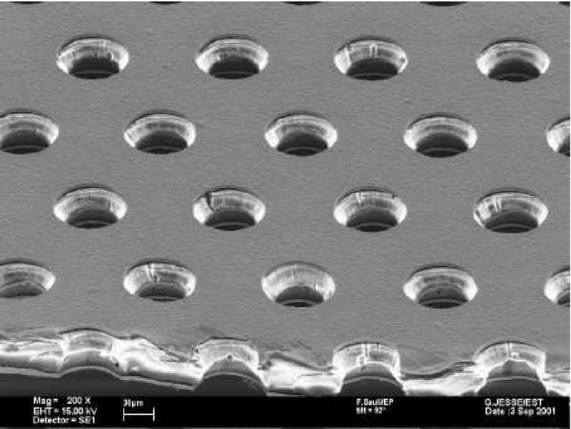
GEMs consist of a thin Kapton foil (about 50 μm) which is coated on both sides with copper layers (about 5 μm). This structure is perforated with holes that typically have a diameter of 70 μm and a pitch of 140 μm. The holes are arranged in a hexagonal pattern. Due to an etching production process they have a double conical shape with an inner diameter of about 55 μm. Figure 1a shows a picture of a GEM that has been taken with an electron microscope.
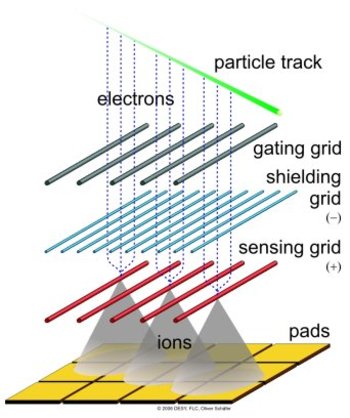
The working principle of a GEM is illustrated in Figure 1b. Between the two copper coatings a voltage of a few 100 V is applied. Since the field lines are focused in the holes, there the resulting electric field strength is in the order of some 10 kV/cm, which is high enough for the gas amplification to happen. It is possible to achieve an amplification up to ten thousand in a single GEM.
But usually, a setup consists of two or three successive GEMs, with a lower amplification per GEM but the same or higher amplification in the hole system. The single GEMs are operated at a lower voltage, which lowers the probability of sparking in the GEM holes. In this way the setup can be operated very stable.
The field configuration is usually chosen in a way that most electric field lines end on the side towards the cathode, while on the other side most lines go into the direction of the anode. Then, most of the ions from the gas amplification are pulled to and collected on the GEM surface while most of the electrons are extracted out of the GEM holes towards the anode. The electron extraction can be intensified if additionally a magnetic field is applied perpendicular to the GEM plane – as it is the case in Time Projection Chambers. The electrons tend to follow rather the magnetic field lines while the ions – due to their higher mass – still rather follow the electric field lines.
Amplification with Wires
In this section, the traditionally used wire gas amplification technique is introduced to illustrate the differences and the advantages of using GEMs for our project.
In previous Time Projection Chambers (TPC) and some current implementations, proportional wires have been and are still used as a device for gas amplification. In this technique, tense parallel wires are mounted in front of the pad plane. These wires are on such a pontential, that the arriving electrons are accelerated in their field, gaining energy to the magnitude where ionization happens.
The produced ions drift back into the TPC volume and induce a (very broad) signal on the pad plane behind the wires. So the signal is measured at the wires and (to improve the resolution) also at the pad plane. Since ions in the TPC volume should be avoided, a second layer of wires (which is called the gate) is necessary. When the gate is open the gating wires are at the same potential as the field in this region. In this state, drifting electrons (and ions) pass this grid without disturbance. To close the grid (which is the normal state) and collect the ions, the potential of neighbouring wires is set alternating to ± 50-100 V. At this setting, the drifting ions and electrons are collected on the wires.
Some drawbacks of this technique have led to the development of new amplification structures, the so-called Micro-Pattern Gaseous Detectors (MPGDs). Two different technologies of micro-pattern devices are under investigation for their use in a TPC in a detector at the ILC: the Micro Mesh Gaseous Detectors (Micromegas) and the GEMs. We at the FLC-TPC group work on the GEM technology.
Disadvantages of Proportional Wires
With proportional wires, the signal is very broad and the distance between two wires is mechanically limited. This makes it difficult to separate two nearby tracks and set limits to the possible rφ and time resolution.
A second disadvantage is the high material budget of the support structures that hold the wires. To provide a perfectly parallel alignment the wires have to be mounted under very high tension. This demands for a very solid mounting system with a high material budget.
Third, the gating is problematic in experiments with a high event rate, where the time between two events is too short for the gating and measurement cycle. If the events do overlap, which means the drift needs longer than the time between two events, gating becomes impossible.
In the case of the ILC all these three problems are realized. A good two-track separation and precise time resolution is needed to achieve the physics goal of the project. To be able to make a very precise energy measurement in the calorimeter, the material budget is very limited. Furthermore, the collision rate is so high that the gating with a grid would not work anymore. Therefore a new amplification technique is needed, that will be described in the next section.
Advantages of GEMs
The GEM technology provides the possibility to avoid the problems mentioned in the previous section. The above mentioned intrinsic ion back-drift suppression is one of the main advantages of the GEMs and makes a gating grid unnecessary. In this way, a detector can be read out continuously using GEMs without the dead time during the gating.
Another advantage of the GEM amplification is the fast signal: the electron signal is measured directly on the pad plane, which leads to a better time (respectively z-) resolution. Furthermore, the GEMs do require less mounting structures as proportional wires do.
The GEM signal on the pad plane is narrower than in the case of proportional wires. This is an advantage in the two-track separation, but poses new problems in the rφ resolution. The pads have to be smaller, so that a narrow signal still hits enough pads for a good reconstruction in the rφ plane. However, the number of pads is limited by the feasible number of readout channels and the signal height (smaller pads result in a smaller signal per pad), so a compromise has to be found.
Overall, GEMs are a very promising technique for the gas amplification in a TPC and many of their advantages already have been confirmed experimentally.