

TPC
Time Projection Chamber
The time projection chamber has been introduced in 1976 by D.R. Nygren. It consists of a gas filled sensitive volume, usually with a central cathode that divides the volume into two identical halves. Each side has an anode with a readout system. The cathode is at a potential that results in a field strength of some 100 V/cm while the anode is at ground potential (typically, this leads to a potential of some 10 kV at the cathode. In 4π-detectors (detectors that cover nearly the whole solid angle) at high energy experiments, the drift volume is usually cylindrical and the beam pipe goes through the rotation axis of the TPC with the interaction point being at the center.
Measurement Principle
A charged particle traversing the gas volume of the TPC will ionize the atoms of the gas mixture (usually around 90% noble gas and 10% quencher) along its trajectory, see point 1 in Figure 1. A high electric field is applied between the endplates of the chamber. The released electrons drift in this field towards the anode, see point 2 in Figure 1.
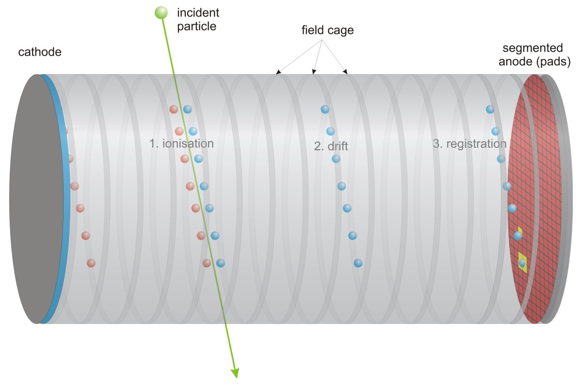
To be able to measure the position of the particle trajectory as accurately as possible, the electric field has to be very homogenous. This can be achieved by a field cage, which usually consists of conducting rings around the cylinder. These rings divide the potential from the cathode stepwise down to the anode.
Additionally, a high magnetic field parallel to the electric field is used to "bend" the trajectory of the particle on a spiral track due to the Lorentz force. This gives the possibility to calculate the momentum of the particle from the knowledge of the curvature and the B-field.
At the anode plane, the electrons can be detected on the readout plane which is segmented in the directions perpendicular to the drift direction, see point 3 in Figure 1. As the electron signal from the primary ionization process is only of the order of 100 electrons per centimeter, the signal needs to be amplified before being detectable. Traditionally this has been done within high electric field in vicinity of thin wires.
The rφ position (coordinates perpendicular to the cylinder axis) of the trajectory can be reconstructed directly from the coordinates of its projection on the pad plane. The z position (coordinate along the cylinder axis) is reconstructed from the drift time (time between particle passing the TPC volume and measured signal on the pads). Therefore an external timing information, e.g. from a silicon detector, is needed.