

GEM Module
After proof-of-principle tests of GEM amplification for a Time Projection Chamber (TPC) at the ILD detector with small prototypes, our group developed a GEM based readout module for the Large Prototype TPC. The anode end plate of this prototype can be equipped by up to 7 readout modules with a size of about 17 cm times 23 cm. This provides a test bed that is similar to the final ILC TPC design, whose end plate will also be covered in a very similar way by many readout modules of a comparable size.
The goal of the module development is to move from basic applicability tests of the technology to the development of a readout for a large scale TPC and to demonstrate the performance required by the ILD project.
The main goals in the development of the readout module are:
- to minimize the material budget of the module structure, so that the particles can propagate as undisturbed as possible to the calorimeters behind the ILD TPC endplate.
- to maximise the sensitive area of the module to have a very high hit reconstruction efficiency over the module area.
- to have minimal gaps between the modules to have a high reconstruction efficiency over the complete end plate and to minimize field distortions originating from the gaps.
To reach these goals, an integrated GEM mounting structure was developed in which the GEM foils are glued to thin ceramic frames. By stacking up several layers of frames and GEM foils a light weight self supporting amplification structure can be realized. After first test with 10x10 cm2 GEMs in a small prototype, a readout module based on this technology has been developed. A sketch showing the schematic structure of the module is shown in Figure 1a. A fully assembled module of the second generation is shown in Figure 1b.

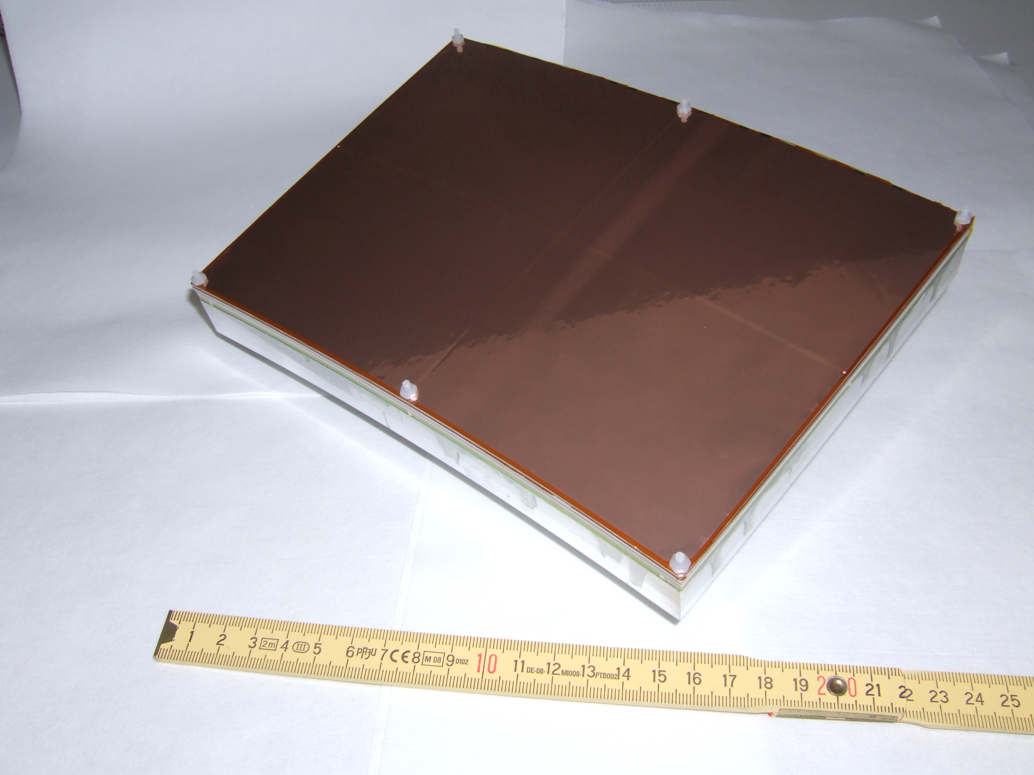
The ceramic mounting frames shown in Figure 1a lead to an insensitive area of about five percent across a GEM foil. Considering a gap of 1mm between two modules, this results in a number of about six percent over the complete readout module. So, 94 % of the readout endplate would be sensitive area. Without readout electronics, the material budget of the readout module adds up to about 8 % of a radiation length.
To increase the field homogeneity along the gaps between the modules the second generation incorporated a field shaping ring around the upper edge of the module, that consisted of a thin wire fixed to the edge of the topmost grid. Since simulation studies have show that a strip should give better results over a wire, for the third generation a metal coating of the outer face of the grid is foreseen instead.