Large Prototype
Introduction
In line with the EUDET programme the FLC TPC Group at DESY in collaboration with the Department of Physics of the University of Hamburg has constructed the field cage of a large TPC prototype (LP). The construction of the LP has been performed in combination with the installation of a superconducting magnet (PCMAG) which hosts the LP in the test beam at DESY.
The Setup
Figure 1a and 1b show a sketch of the setup and the result of a magnetic field calculation. The magnet was installed in the DESY electron testbeam area in December 2006. Additionally to the LP, silicon strip detectors will be installed. These will give two independent external reference points when shooting electrons through the TPC.


As LP is foreseen to fit into the PCMAG, the dimensions of its field cage are restricted by the magnet's geometry. The outer diameter of the field cage was designed to be 77 cm leaving a gap of 3.5 cm to the inner wall of the magnet, which has a diameter of 85 cm. This space is sufficient for the installation of the silicon strip detectors.
The length of the field cage measures 61 cm. The reason why the field cage is comparably short to its diameter is the magnetic field which is homogeneous only within 3% only in a range of ±30 cm around the magnet's center.

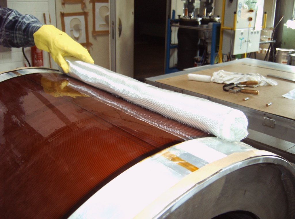
The field cage is very lightweight but nevertheless stable. Its structure is made of composite materials which have already been used for the construction of the MediTPC. The thickness of the wall profile was estimated to be about 1.21% of a radiation length X0.
Figure 3 shows the technical drawing of the fieldcage. This can also be downloaded in higher resolution in this PDF file of technical drawing of Large Prototype fieldcage.

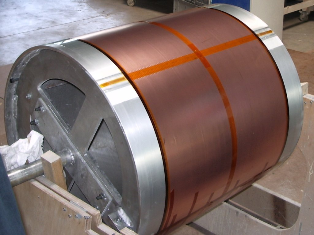
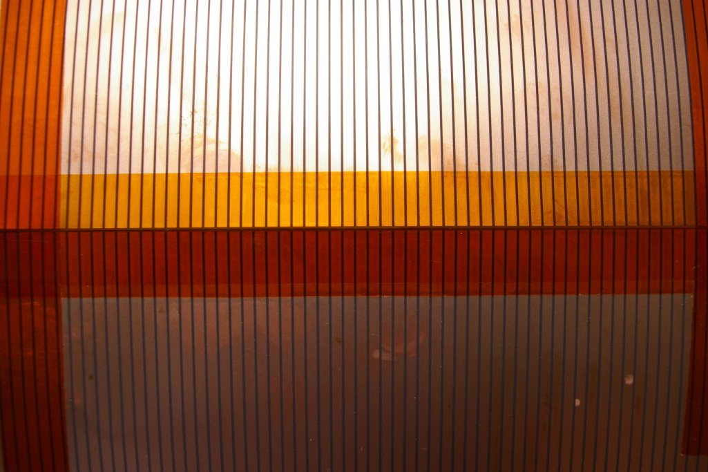
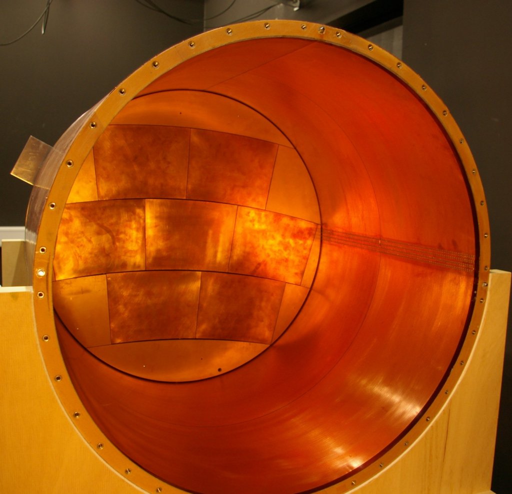
The field cage has been produced on a special cylinder with a diameter of 72 cm. In Figure 4 this mandrel is shown with the first layer attached of the wall attached. This first layer carries copper rings which provide a very homogeneous electric field in the sensitive volume.
In the following the other layers of the wall (compare Figure 2) have been glued onto the mandrel. In a final step, the diameter of the mandrel was slightly reduced to remove the finalized chamber smoothly.
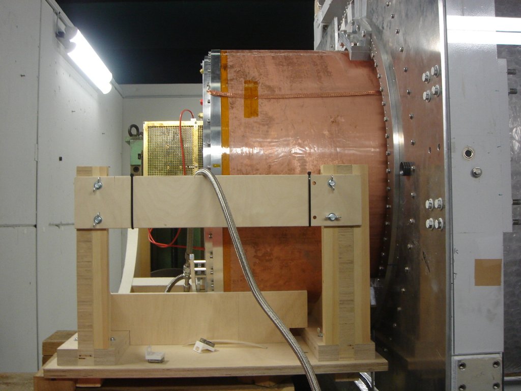
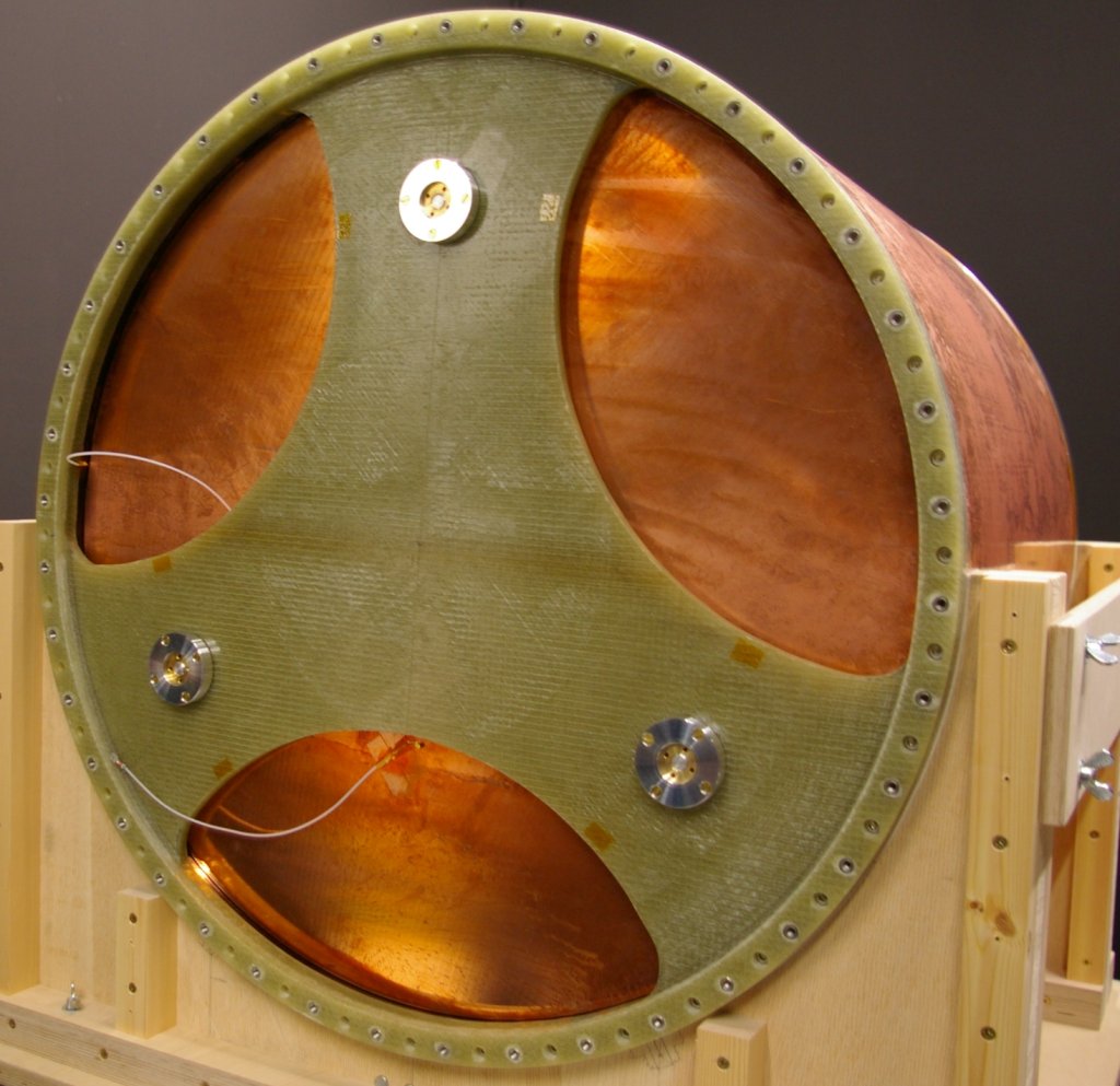
The field cage was produced between May and August 2008 and afterwards it was commissioned at DESY. Complementary to the field cage, a cathode end plate has been set up (see Figure 5) which is mounted on an intermediate flange. There it is held by a three point mounting which allows for an alignment of the cathode surface relative to the anode.
A first iteration anode end plate, which can house up to seven read-out modules of a size comparable to the one planned for the final ILD TPC, has been designed and constructed at the University of Cornell and was joint with the field cage in November 2008. On the web page of Cornell, you can find more information about the anode end plate. Figure 6 shows the first assembly of the field cage into the PCMAG.
After first test beam runs in December 2008 and January 2009 (see Figure 6), the LP field cage has been in regular use by different research groups.